







A machine can complete factory acceptance testing and still lose days at the customer’s site because its electrical verification was treated as a final inspection rather than a design-controlled process. EN 60204-1 provides the relevant framework for the electrical equipment of machinery, but commissioning depends on more than citing the standard. Manufacturers and integrators need defined acceptance criteria, current drawings, suitable instruments, assigned responsibilities and enough time to correct faults before production pressure takes over. The following ten failures are common reasons why energisation, validation and handover do not proceed as planned.
Start with scope, documentation and visible identification
1. The verification boundary is unclear. Commissioning often begins without agreement on what is being assessed: a standalone machine, several interconnected modules or an assembly sharing supplies and protective functions. Interfaces introduced by conveyors, external control panels, utilities and upstream or downstream equipment can alter the verification scope. Define the machine limits, supply characteristics, operating modes and integration interfaces before testing. The boundary should also correspond with the risk assessment under ISO 12100 and the responsibilities assigned to the manufacturer and integrator.
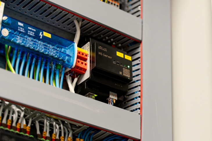
2. Drawings do not match the installed machine. Late substitutions, site modifications and improvised terminal changes frequently remain marked only on workshop prints. The result is a cabinet that may operate but cannot be verified efficiently or maintained with confidence. Using a practical EN 60204-1 electrical-equipment checklist helps the team compare schematics, terminal plans, cable schedules and parts lists with the as-built installation before formal testing starts. Deviations should be resolved or documented rather than passed to the customer as unexplained commissioning notes.
3. Conductors and components are identified inconsistently. Missing wire numbers, duplicated device tags and unclear terminal markings slow fault-finding and increase the chance of intervention on the wrong circuit. Protective and neutral conductors also require correct identification. Inspect labelling at both ends of conductors and compare it with the drawings, including field devices, junction boxes and detachable assemblies. Labels must remain legible in the expected industrial environment, not merely during a clean workshop inspection.
Verify the protective path before functional trials
4. Protective bonding is assumed rather than measured. A visible green-and-yellow conductor does not demonstrate an effective protective circuit. Painted frames, hinged doors, removable panels, flexible machine sections and assemblies mounted through insulating materials can interrupt continuity. Verification should cover accessible conductive parts and account for the actual construction of the machine. Record the measurement method, instrument and results so that failures can be located and corrected rather than reduced to a simple pass-or-fail statement.
5. Protection against electric shock is checked without the real supply conditions. Protective-device selection and disconnection behaviour depend on the supply arrangement, earthing system, circuit characteristics and connected equipment. Drives, filters and other power-electronic devices can also influence leakage current and the suitability of residual-current protection where it is used. Confirm the customer’s supply data early, then verify that the installed protective measures correspond to the design assumptions. A machine should not reach site with unresolved questions about fault protection or upstream protective coordination.
Test circuits under fault and stop conditions
6. Short-circuit and overload protection is not coordinated with the installed conductors and loads. A protective device may have the expected rating yet still be unsuitable for the cable, motor, drive or prospective fault conditions. Conversely, overly sensitive selection may produce nuisance trips during acceleration or normal process peaks. Review conductor capacity, load data, device characteristics and supplier requirements as one protection chain. Any component substitution made during assembly should trigger a focused design review rather than an assumption of equivalence.
7. Emergency-stop and protective-stop behaviour is tested only in normal operation. Pressing each red mushroom button once is not enough. The test plan should cover all affected actuators, operating modes, reset behaviour and restoration of power. It should also confirm that a reset does not itself initiate hazardous motion. Where safety-related control functions are involved, validation must follow the defined architecture and performance requirements, including relevant ISO 13849 considerations. Results should be traceable to individual functions rather than recorded as a generic statement that the safety circuit works.
8. A software change is introduced after verification without assessing its impact. Changes to PLC logic, drive parameters, HMI mode selection, interlocks or restart sequences can invalidate earlier results even when no wiring has changed. Commissioning teams need version identification, approval criteria and a defined regression-test scope. The same discipline used for controlled software updates in production environments should apply before handover: identify what changed, determine which safety assumptions may be affected, test the relevant functions and retain evidence of the accepted version. Software management does not replace functional-safety validation or the manufacturer’s responsibility.
Do not overlook installation quality and maintainability
9. Cable routing and electromagnetic compatibility are reviewed only after unstable operation appears. Mixing motor and signal cables, terminating shields inconsistently or creating unsuitable bonding paths can produce intermittent sensor readings, communication faults and unexplained stops. These symptoms are often misdiagnosed as software defects. Inspect segregation, shielding, grounding and cabinet layout before prolonged functional trials. The objective is not simply tidy wiring, but predictable behaviour in the machine’s intended electromagnetic environment.
10. Access, lighting and service conditions are excluded from electrical acceptance. Verification may show that circuits operate correctly while maintenance personnel still cannot safely identify terminals, inspect components or work in enclosed machine areas. Check cabinet clearances, component accessibility, internal machine lighting where adjustment or maintenance is expected, and the readability of warnings and labels. These practical details influence whether the verified design remains serviceable after commissioning.
Turn verification into a controlled commissioning gate
Electrical verification should be planned as a sequence: establish the machine boundary, freeze the relevant design baseline, inspect the installation, perform the required measurements, validate functions and close deviations before release. Each stage needs an owner and objective evidence. Instruments should be suitable for the measurement and under the organisation’s measurement-control arrangements, while records should identify the tested machine configuration and date.
The approach is especially important for retrofits and relocated equipment. A pre-commissioning review of undocumented machinery may reveal that old drawings, previous modifications and the installed safety logic no longer describe the same configuration. In that situation, testing cannot begin from assumptions. The team must first reconstruct enough technical information to define the verification scope and decide which circuits or functions require redesign, replacement or further analysis.
A failed test is not merely a documentation inconvenience. It is evidence that an assumption, installation detail or protective measure needs attention. Treating failures through a controlled deviation process prevents informal fixes from becoming part of the delivered machine. Correct the cause, update the drawings and software records, repeat affected tests and obtain acceptance from the responsible engineering functions.
EN 60204-1 verification is most effective when it is integrated with risk reduction, safety-control validation and commissioning management. It cannot by itself establish the conformity of an entire machine, nor does a completed checklist guarantee safe operation in every application. It does, however, provide a disciplined way to expose electrical defects before operators, maintenance teams and production schedules inherit them. For manufacturers and integrators, that is the practical route to a more predictable handover: define the evidence early, verify the installed configuration and never allow production urgency to become an acceptance criterion.